STORM32 Gimbal Setup
STORM32BGC is a popular open-source three-axis gimbal controller. This guide covers wiring and ArduPilot parameter setup with the SparkNavi Blue.
Hardware Specs and Power
- Voltage: STORM32 main board accepts 10 V – 16.8 V input; a 3S Li-Po battery is recommended (4S is also supported up to 16.8 V full).
- Current: 0.5 A (gimbal control board only — motors are separate)
- GUI software: STORM32 BGC Tool v0.90 (older but stable)
⚠️ Use v0.90 GUI for tuning; newer GUI builds have compatibility issues with older STORM32 firmware.
Wiring Map
| Gimbal Axis | SparkNavi Blue Pin | ArduPilot Parameter | RC Channel |
|---|---|---|---|
| PITCH | AUX1 | SERVO9_FUNCTION |
RCIN9 |
| ROLL | AUX2 | SERVO10_FUNCTION |
RCIN10 |
| YAW | AUX3 | SERVO11_FUNCTION |
RCIN11 |
| Lock / Follow | AUX4 | SERVO12_FUNCTION |
RCIN6 |
Lock mode locks the yaw axis to a fixed direction (e.g., forward); when enabled, the camera stays pointed in that direction regardless of how the aircraft rotates. Most typical applications use Lock mode.
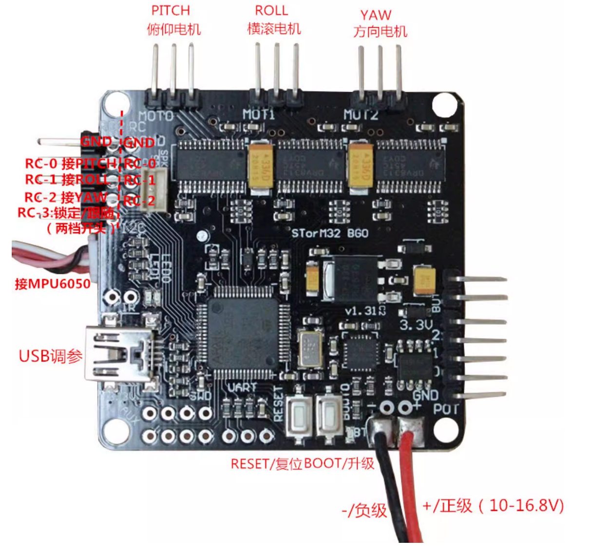
STORM32 Board Wiring Reference
The image below shows the STORM32 BGC board pinout. RC-0 / RC-1 / RC-2 receive PITCH / ROLL / YAW signals. USB is for tuning.
STORM32 GUI Tuning
Connect the STORM32 BGC to your computer via mini USB and open STORM32 BGC Tool v0.90:
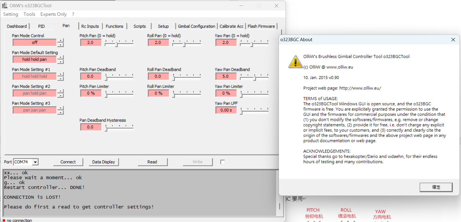
Adjust parameters on the PID (stability) and Pan (auto-follow) tabs. Tuning values vary by gimbal model. Stiffer PID values give better wind / disturbance rejection, but cause the motors to heat up rapidly.
ArduPilot Configuration
1. Verify RC Channels
In Mission Planner Setup → Mandatory Hardware → Radio Calibration, confirm Radio 9 / 10 / 11 respond to your transmitter knobs.

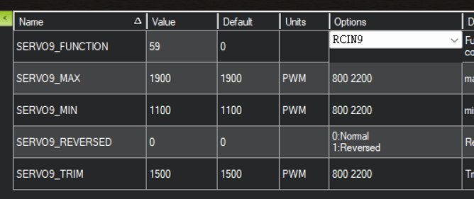
2. Set SERVO Functions
In Config → Full Parameter List:
| Parameter | Value | Description |
|---|---|---|
SERVO9_FUNCTION |
59 (RCIN9) |
PITCH passthrough from RC 9 |
SERVO10_FUNCTION |
60 (RCIN10) |
ROLL passthrough from RC 10 |
SERVO11_FUNCTION |
61 (RCIN11) |
YAW passthrough from RC 11 |
SERVO12_FUNCTION |
56 (RCIN6) |
Lock / Follow toggle from RC 6 |
You may also adjust PWM ranges:
| Parameter | Default | Description |
|---|---|---|
SERVO9_MIN |
1100 |
Minimum PWM |
SERVO9_MAX |
1900 |
Maximum PWM |
SERVO9_TRIM |
1500 |
PWM mid |
SERVO9_REVERSED |
0 or 1 |
Reverse direction |
Same approach for SERVO10–SERVO12.
Using Lock Mode
After setup, flip the RC6 switch on your transmitter (typically a 2-position switch):
- OFF: Follow mode — gimbal follows the aircraft attitude
- ON: Lock mode — gimbal YAW locked to the current heading; the camera stays fixed when the aircraft rotates