IMU600-V2
IMU600-V2 Online Setup Guide · Online Communication Protocol
GNSS/INS Core · Triple-IMU Array Inertial Module
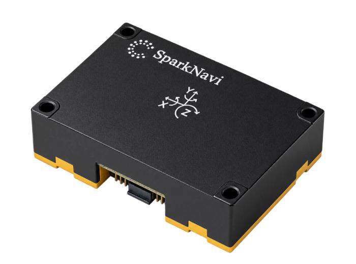
IMU600-V2 is the inertial core of SparkNavi InertiaX GNSS/INS systems. It combines three 6-axis MEMS IMUs and outputs fused angular rate, specific force, delta angle (Δθ) and delta velocity (Δv). Built-in AHRS, a barometer, GPS PPS time alignment and external triggering support system integration. The three IMUs are compared in real time; a faulty IMU can be excluded automatically without interrupting the output.
The module provides inertial measurements and attitude for integration into a navigation system. GPS PPS is a time-synchronization input.
| Gyro ARW | Gyro bias instability | Accel bias instability | Max. IMU output |
|---|---|---|---|
| 0.015 °/√h | 0.35 °/h | 12 µg | 1000 Hz |
Performance figures below are typical values from the datasheet, Preliminary Rev. 1.1 (October 2026), not guaranteed limits. Test conditions are listed below.
Download PDF · Datasheet · Downloads
Key Features
- Triple-IMU array fusion: approximately 1.7× lower noise than a single IMU, with real-time fault detection and exclusion.
- Δθ / Δv output with coning and sculling compensation.
- Built-in AHRS with quaternion and Euler-angle output, plus automatic gyro bias calibration when stationary.
- Multi-position static gyrocompassing without a magnetometer or GNSS.
- Independent IMU and barometer output rates; IMU output up to 1000 Hz.
- Dual UART with ASCII / binary formats, SPI slave interface, GPS PPS and external trigger.
- Windows GUI for live monitoring, configuration, six-face accelerometer calibration and encrypted, signed firmware updates.
Inertial Performance
| Parameter | Typical value / specification |
|---|---|
| Sensors | 3 × 6-axis MEMS IMU + 1 × barometer |
| Gyroscope range | ±300 °/s |
| Gyro angle random walk (ARW) | 0.015 °/√h |
| Gyro noise density | 0.00025 °/s/√Hz |
| Gyro bias instability | 0.35 °/h |
| Accelerometer range | ±16 g |
| Velocity random walk (X / Y) | 0.02 m/s/√h |
| Velocity random walk (Z) | 0.1 m/s/√h |
| Accel bias instability | 12 µg |
| Internal sample rate | 1475 Hz per IMU |
| Coordinate frame | Body FRD (Forward, Right, Down) |
AHRS & North Finding
| Parameter | Typical value / specification |
|---|---|
| Attitude output | Roll / pitch / heading; quaternion and Euler angles |
| Roll / pitch static noise (1σ) | 0.003° |
| Roll / pitch static peak-to-peak (1 h) | 0.02° |
| Static heading hold (1 h) | < 0.02° |
| Automatic gyro bias calibration | At power-up and after 10 seconds stationary |
| North-finding method | Multi-position static gyrocompassing |
| North-finding accuracy (1σ, latitude 23°) | 0.76° |
| Alignment time | Approximately 25 minutes (4–5 headings × approximately 5 minutes) |
AHRS heading is relative until an initial heading is set. The static heading-hold figure is measured with automatic gyro bias calibration enabled while the unit is stationary; it does not specify heading accuracy during motion.
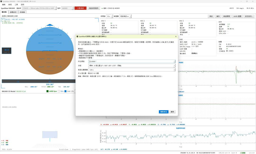
For north finding, place the unit level on a rigid, vibration-free surface and rotate it about the vertical axis by roughly 90° between stationary measurements. After alignment, set the AHRS heading by command to obtain true-heading output. Performance depends on latitude and degrades at higher latitudes.
Barometer
| Parameter | Typical value / specification |
|---|---|
| Pressure range | 300–1250 hPa |
| Absolute accuracy (300–1100 hPa, −5 to +65 °C) | ±0.3 hPa |
| Relative accuracy (700–1100 hPa, +15 to +55 °C) | ±0.06 hPa (approximately ±0.5 m) |
| Temperature coefficient of offset | ±0.5 Pa/K |
| Long-term stability (12 months) | ±0.1 hPa |
| Pressure noise (RMS, 50 Hz output) | 0.15 Pa (approximately 1.3 cm) |
| Output rate | 10 / 25 / 50 (default) / 100 Hz |
| Output data | Pressure, temperature and ISA barometric altitude |
Range, accuracy, temperature coefficient and long-term stability are pressure-sensor element specifications. Absolute accuracy excludes post-assembly soldering offset. Pressure noise was measured indoors with the unit stationary at 50 Hz output. Barometric altitude uses the ISA sea-level pressure of 1013.25 hPa.
Outputs & Interfaces
| Parameter | Typical value / specification |
|---|---|
| IMU output rates | 5 / 10 / 25 / 50 / 100 / 200 / 400 / 500 / 1000 Hz |
| Output data | Angular rate, specific force, Δθ, Δv, temperature, AHRS attitude and pressure |
| UART1 (primary) | 3.3 V TTL; 460800–2000000 bps; ASCII / binary |
| UART2 (secondary) | 3.3 V TTL; 115200–2000000 bps; output only |
| SPI flight-controller interface | 3.3 V slave; Mode 3 / Mode 0; 2 MHz SCK recommended |
| SPI packet | 128 bytes with CRC-16; fused and per-IMU Δθ / Δv |
| GPS PPS input | 3.3 V, rising edge, 1 Hz ±1000 ppm, pulse width ≥1 µs |
| Time alignment | Output grid aligned to the PPS rising edge |
| Timestamp resolution | 1 µs |
| External trigger | One output per rising edge; 1–1000 Hz recommended |
ArduPilot Integration
The SPI interface can be used as an external IMU for ArduPilot with a driver supplied by SparkNavi. The datasheet documents verification on a SparkNavi Blue2 with Copter 4.7.1, using IMU600-V2 as the third SPI IMU at a 2 MHz SPI clock.
Set the SPI output mode to ardupilot and the IMU output rate to 1000 Hz. This is the configuration documented for the ArduPilot integration. SPI and UART outputs operate independently. Contact SparkNavi for the driver and integration details.
Mechanical, Electrical & Environmental
| Parameter | Typical value / specification |
|---|---|
| Supply voltage | +5.0 V |
| Power consumption | 0.73 W |
| Dimensions (L × W × H) | 44.0 × 30.6 × 14.45 mm |
| Weight | 25 g |
| Operating temperature | −40 to +85 °C |
| Storage temperature | −40 to +85 °C |
Performance Data & Test Conditions
Allan-deviation data: approximately 25 hours stationary at room temperature, 5 Hz Δθ / Δv output, fused IMU-array output. AHRS data: one hour stationary at room temperature with 5 Hz output, excluding the first 60 seconds after AHRS reset. North-finding data: an indoor bench in Tainan at latitude 23°, five headings of about five minutes each, 50 Hz output, 29 minutes total.
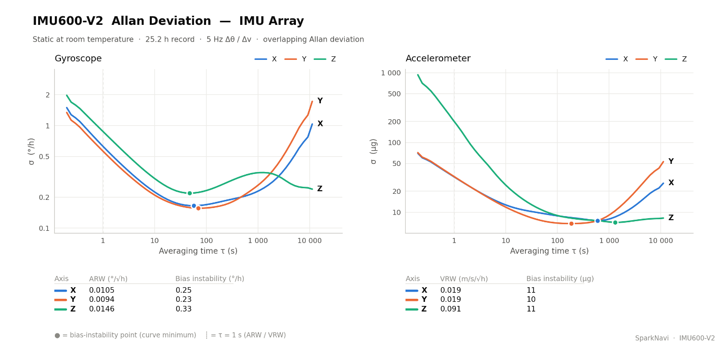
IMU-array Allan deviation
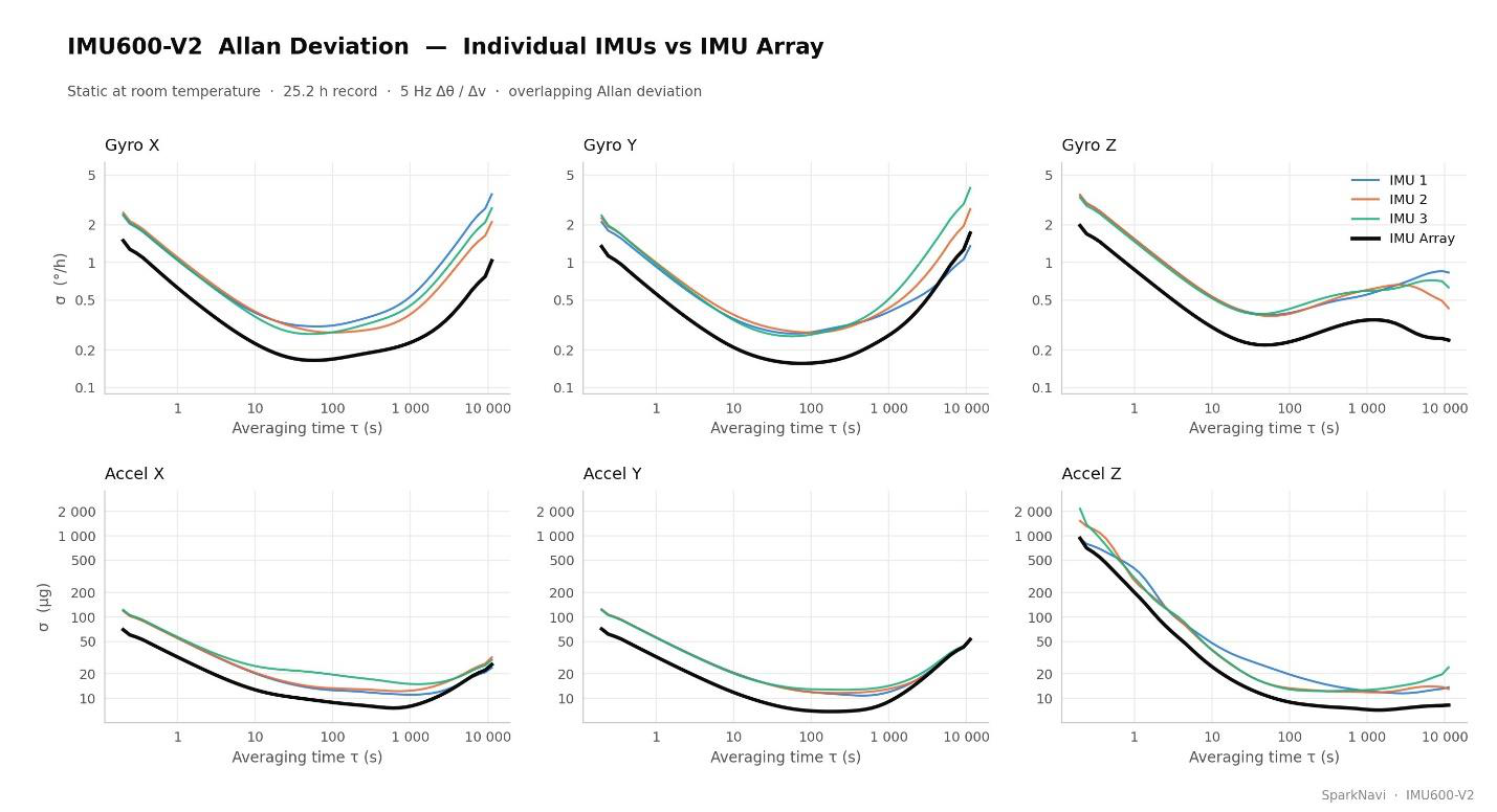
Individual IMUs compared with array fusion
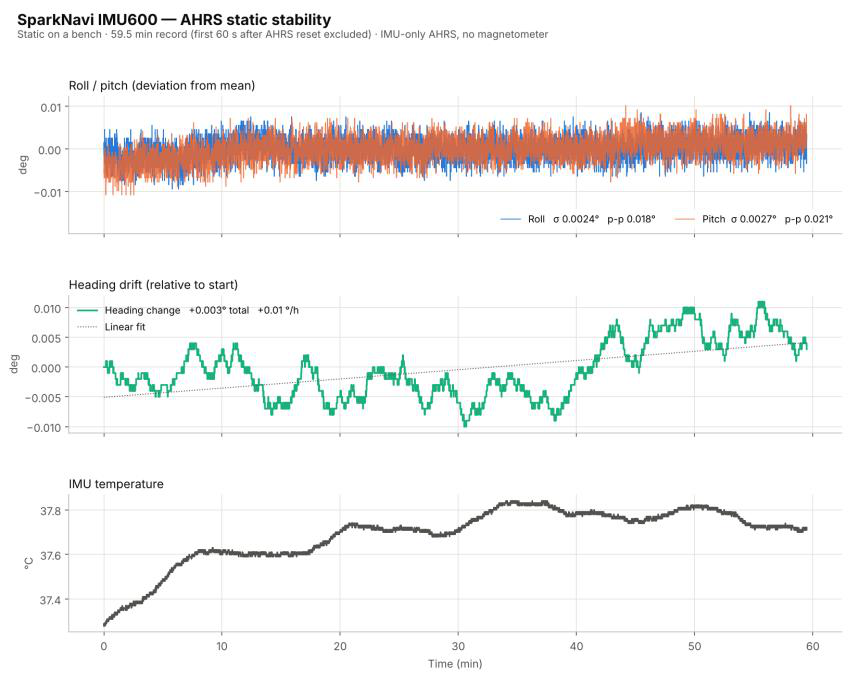
AHRS static stability
Configuration & Monitoring Software
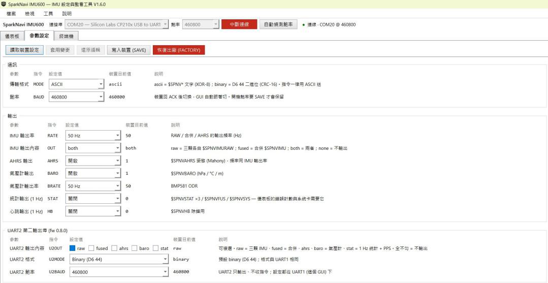
SparkNavi IMU600 GUI for Windows provides a live AHRS dashboard, 3D view, per-IMU status and measurement plots. It supports output-rate and interface configuration, saving settings to the device, a guided north-finding workflow, six-face accelerometer calibration, data recording and firmware updates.
GUI software is available on request. Contact ethan@robotlab.com.tw
Downloads
| Resource | Version / language | Download |
|---|---|---|
| Datasheet | Preliminary Rev. 1.1 · Chinese / English | Download PDF |
| User manual | v1.1 · Traditional Chinese · firmware 0.11.2 | Download PDF |
| Communication protocol | v1.1 · Traditional Chinese · firmware 0.11.2 | Download PDF |
GUI software is available on request. Contact ethan@robotlab.com.tw
For samples, quotations or integration support, contact ethan@robotlab.com.tw