Pinout, Power & Coordinates
For IMU600-V2 / firmware 0.11.2 / GUI v1.6.1.
Power & Signal Levels
- Power input is +5 V ±5%. UART, SPI, PPS and EXT_TRIGGER use 3.3 V logic. The 5 V supply rating does not apply to signal pins.
- J1 is a Samtec MW-12-03-G-D-130-110, 2 × 12 connector. Identify pin 1 on the underside and the odd/even rows in the diagram. Connect ground at pin 1 / 2 and share ground with the host.
- Cross UART TX → RX and RX ← TX. Use level conversion for a 5 V host. A USB-UART adapter supporting at least 921600 bps is recommended, such as a suitably configured FT232H / CP2102N.
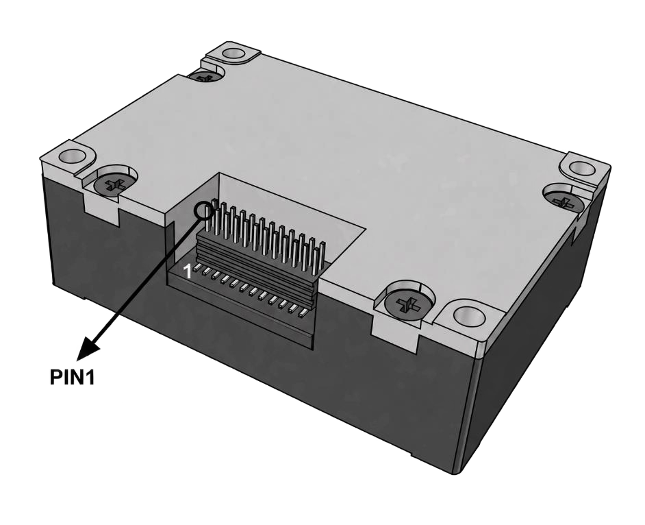
Module underside and pin 1
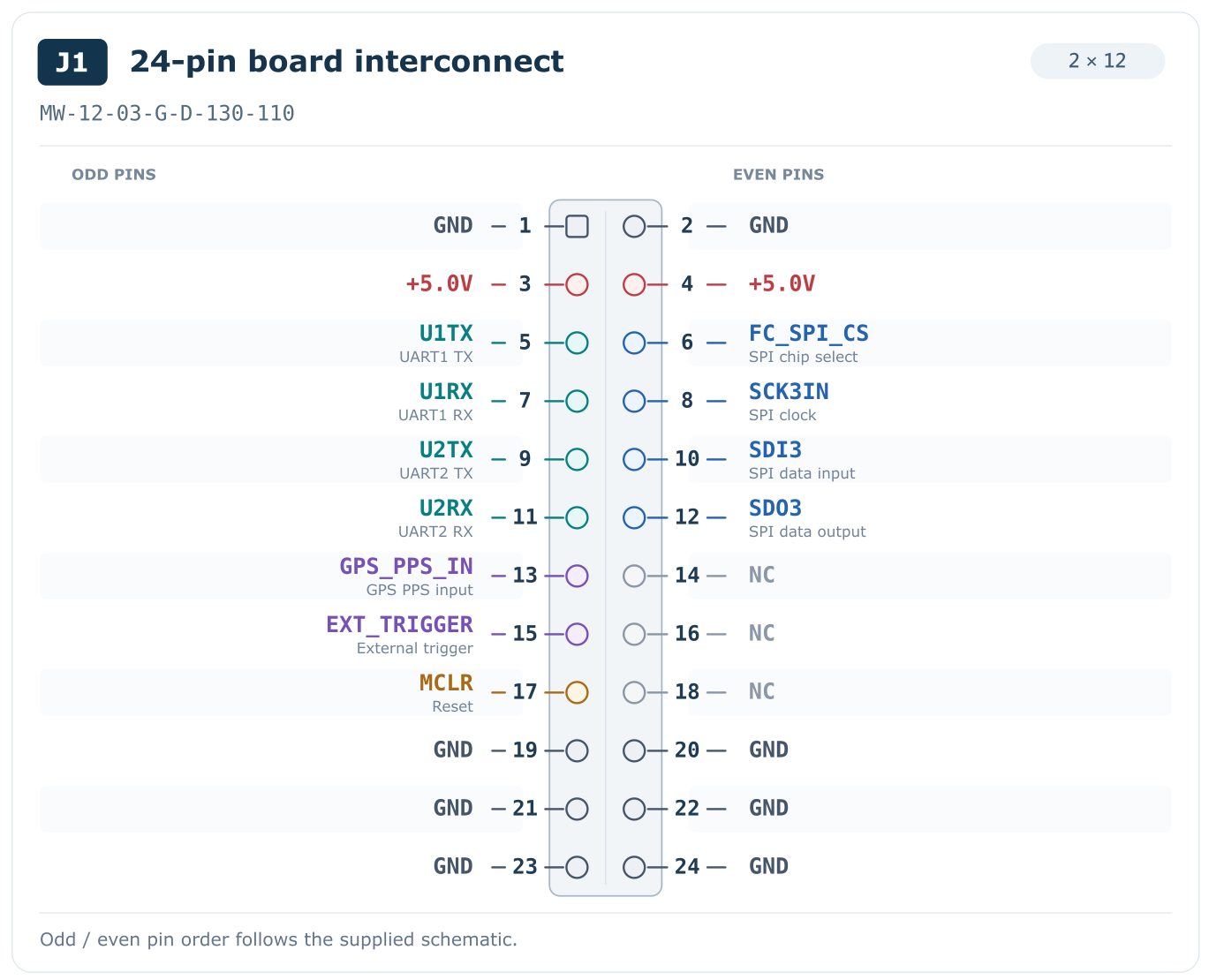
J1 pinout; orient using the physical pin 1 mark
J1 Pin Table
| Pin | Signal | Direction (module) / Purpose |
|---|---|---|
| 1, 2 | GND | Ground |
| 3, 4 | +5V | Power input |
| 5 | U1TX | Output → host RX |
| 6 | FC_SPI_CS | Input; SPI CS, active low |
| 7 | U1RX | Input ← host TX; commands |
| 8 | SCK3IN | Input; SPI clock |
| 9 | U2TX | Output; second data port |
| 10 | SDI3 / MOSI | Input; SPI host sends 0 |
| 11 | U2RX | Currently unused; leave open |
| 12 | SDO3 / MISO | Output; SPI data |
| 13 | GPS_PPS_IN | Input; 3.3 V rising edge |
| 14 | NC | No connection |
| 15 | EXT_TRIGGER | Input; 3.3 V rising edge |
| 16 | NC | No connection |
| 17 | MCLR | Input; active-low reset, on-board 10 kΩ pull-up to 3.3 V |
| 18–22 | NC | No connection |
| 23, 24 | GND | Ground |
Unused inputs may be left open. SPI CS has a pull-up; MISO is high-impedance when SPI is off. Leave unused MCLR open and do not drive it high; see reset and maintenance.
Development Board
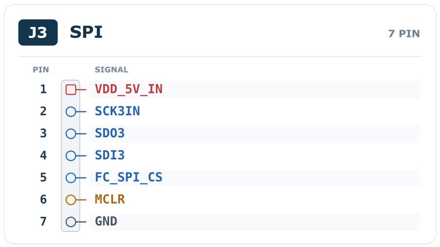
Development-board J3 SPI wiring
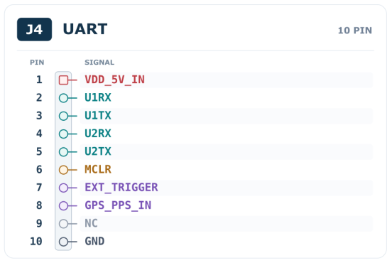
Development-board J4 UART wiring
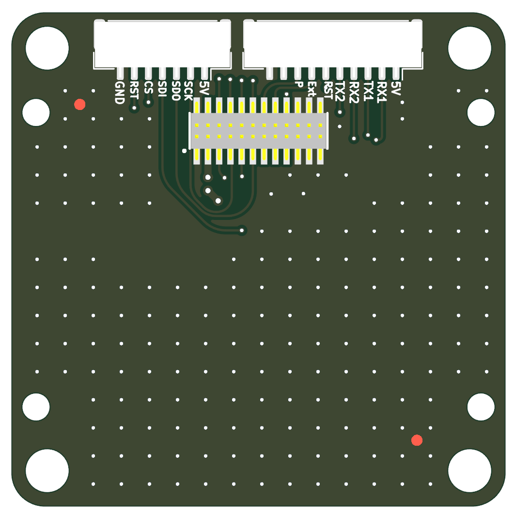
Development-board connector positions
FRD Axes & Mounting
Axes are +X forward, +Y right, +Z down (FRD). AHRS uses ZYX Euler angles; the quaternion maps body FRD → NED with scalar q0. Mount +X forward or apply the corresponding rotation in the host.
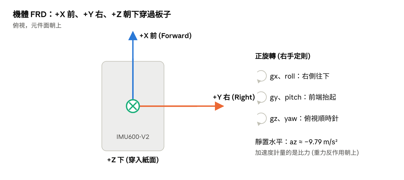
FRD coordinate definition
| Motion / Attitude | Expected Reading |
|---|---|
| Upright, level and stationary | ax ≈ 0, ay ≈ 0, az ≈ −9.79 m/s²; roll / pitch ≈ 0° |
| Right side rotates down | Positive gx / roll; negative ay when held tilted |
| Nose rotates up | Positive gy / pitch; positive ax when held tilted |
| Clockwise viewed from above | Positive gz |
Acceleration is specific force; all three axes will not read zero at rest. Secure the module and control vibration to avoid exceeding ±300 °/s or ±156.9 m/s².
Source document:IMU600-V2 User Manual v1.1 · PDF pages 8–14