UART2, GPS PPS & External Trigger¶
For IMU600-V2 / firmware 0.11.2 / GUI v1.6.1.
UART2 Secondary Output¶
UART2 outputs on J1 pin 9 U2TX, defaulting to 460800 bps, binary, all three RAW IMUs. It can run alongside UART1, for example GUI on UART1 and a navigation computer on UART2. Pin 11 U2RX does not currently accept commands.
- Configure UART2 through UART1: U2OUT selects content, U2MODE format and U2BAUD baud; finish with SAVE.
- Combine raw, fused, ahrs, baro and stat using +, or choose none / all. stat includes 1 Hz statistics and PPS status.
- The ports have independent content switches and binary sequence counters. ACK / NAK / INFO return only on UART1. Overflow discards whole messages; check SYS u2_drop or GUI UART drops (U2 n).
$SPNVCMD,U2OUT,raw+baro
$SPNVCMD,U2MODE,binary
$SPNVCMD,U2BAUD,921600
$SPNVCMD,SAVE,1
This example does not lower RATE; check the bandwidth table for the actual rate. Three RAW IMUs require about 22.5 kB/s at 100 Hz and 225 kB/s at 1000 Hz; the latter exceeds every supported UART baud.
GPS PPS Wiring & Alignment¶
Connect GPS PPS or a precise 1 Hz reference to pin 13 GPS_PPS_IN with common ground. Use 3.3 V rising-edge pulses at least 1 µs wide, never exceeding 3.3 V. PPS defaults to 1; without PPS, output uses a free-running grid.
| Item | Requirement / Behavior |
|---|---|
| Period | Consecutive rising edges 999–1001 ms apart (1 s ±1000 ppm) |
| Lock | Locks after two consecutive valid intervals |
| Noise / Missing Pulses | Too-short intervals are rejected; captures − edges counts rejected captures. Missing 1–9 pulses can retain phase across k = 2–10 second intervals |
| HOLDOVER | After >1.5 s without PPS, extrapolates using the last valid interval |
| Resolution | 50 MHz edge capture has 20 ns resolution; ts_us is still expressed in 1 µs units. Neither alone specifies absolute timing accuracy |
When locked, each PPS second contains RATE output windows; the corresponding RAW status / fused flags has bit7 set. Initial lock adjusts phase once by up to one output period, so that dt may be longer or shorter. The module does not receive GPS time messages: ts_us remains time since boot. The host must associate the marked sample with a GPS UTC second.
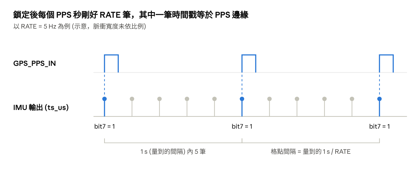
PPS-aligned grid example: RATE = 5 Hz
Check PPS State¶
| state | Name | Meaning |
|---|---|---|
| 0 | OFF | PPS,0; free-running |
| 1 | NO_SIGNAL | No valid reference yet |
| 2 | ACQUIRING | Edges seen, but not two consecutive valid intervals |
| 3 | LOCKED | Aligned |
| 4 | HOLDOVER | Uses last interval; recovers when valid PPS returns |
Enable STAT,1 on UART1 or include stat in U2OUT to receive SPNVPPS on valid edges or state changes. If pps_cnt increases but stays ACQUIRING, measure the actual period: a software-generated “1 Hz” may miss the ±1000 ppm tolerance.
EXT_TRIGGER Input¶
| TRIG | Mode | Output Behavior |
|---|---|---|
| 0 | Continuous (default) | Automatic RATE output; ignores pin 15 |
| 1 | External trigger | Waits for pin 15 rising edges; first edge establishes baseline only |
- Connect a push-pull 3.3 V signal to pin 15 EXT_TRIGGER, with common ground and pulses at least 1 µs wide. The input has a pull-down.
- Enable TRIG,1 and SAVE if required. The first edge produces no sample; each subsequent valid edge outputs the complete integral since the previous edge.
-
Check CFG trig, SYS trig_cnt / trig_rej and the GUI output mode. Restore TRIG,0 when no longer using trigger.
-
ts_us records the trigger edge; dt is actual sample integration time. Sample-based boundaries can differ from the exact edge interval by less than one sample (about 0.68 ms). Successive Δθ / Δv contain adjacent samples without duplication or omission. Output waits up to about 0.7 ms for a sample, plus processing and transport.
- Recommended range is 1–1000 Hz. Edges <0.5 ms apart are rejected; after about 10 s without a trigger, the next edge resets the baseline. AHRS does not update for intervals >1 s.
- RATE does not control IMU output in this mode and PPS grid alignment is inactive; barometer output still follows BRATE. OUT / AHRS / U2OUT still select content. Size bandwidth using trigger frequency.
Protocol Notes: Trigger & PPS Versions¶
The higher-priority trigger interrupt reads the 50 MHz timer to record edge time; integration still operates on raw samples. trig_rej includes both <0.5 ms glitches and trigger-event queue overflow while the main loop is busy.
On PPS return from HOLDOVER, an edge matching the existing integer-second grid can restore LOCKED immediately; otherwise it returns to ACQUIRING. Invalid intervals do not necessarily produce a PPS message each second; also inspect raw pps_cnt.
Firmware ≤0.8.0 kept continuous output and resent the latest sample on a trigger, risking duplicate or missed integration; that behavior was removed. This guide uses true trigger mode in fw 0.11.2. Connector naming follows the user manual’s J1 24-pin diagram; development-board J3 / J4 have different pin numbering.
Communication details also follow Protocol v1.1, pages 26–28. See the protocol overview.
Complete $SPNVPPS Format and Fields¶
$SPNVPPS,<ts_us>,<edges>,<captures>,<state>,<err_ppm>,<age_ms>,<align>*XX
| # | Field | Unit / Meaning |
|---|---|---|
| 1 | ts_us | µs; latest accepted PPS rising edge, using the IMU boot-time clock. |
| 2 | edges | Cumulative accepted edges. |
| 3 | captures | Raw captures including noise; captures − edges counts captures not accepted. |
| 4 | state | 0 OFF / 1 NO_SIGNAL / 2 ACQUIRING / 3 LOCKED / 4 HOLDOVER |
| 5 | err_ppm | ppm; local oscillator error relative to PPS, positive when local clock is faster. Binary uses err_ppb = err_ppm × 1000. |
| 6 | age_ms | ms since the latest accepted edge. Binary u16 caps at 65535 ms. |
| 7 | align | 1 indicates output boundaries aligned with PPS. |
XX is a checksum placeholder; actual lines end in CRLF. Measured PPS interval divided by RATE determines next-second output spacing; ts_us does not become UTC. A 993.83 mHz source (about 6200 ppm error) increments pps_cnt but does not lock.
Trigger mode retains RATE for returning to TRIG,0; statistics remain once per second. Connector labels conflict: protocol §12 says J2 and §13 J3, while the manual labels the module connector J1. Use the module J1 24-pin drawing, pin 15 and pins 6/8/10/12, separately from carrier-board J3/J4.
Source document:IMU600-V2 User Manual v1.1 · PDF pages 28–31